EV 2025
MY ROLECAD & vehicle testing
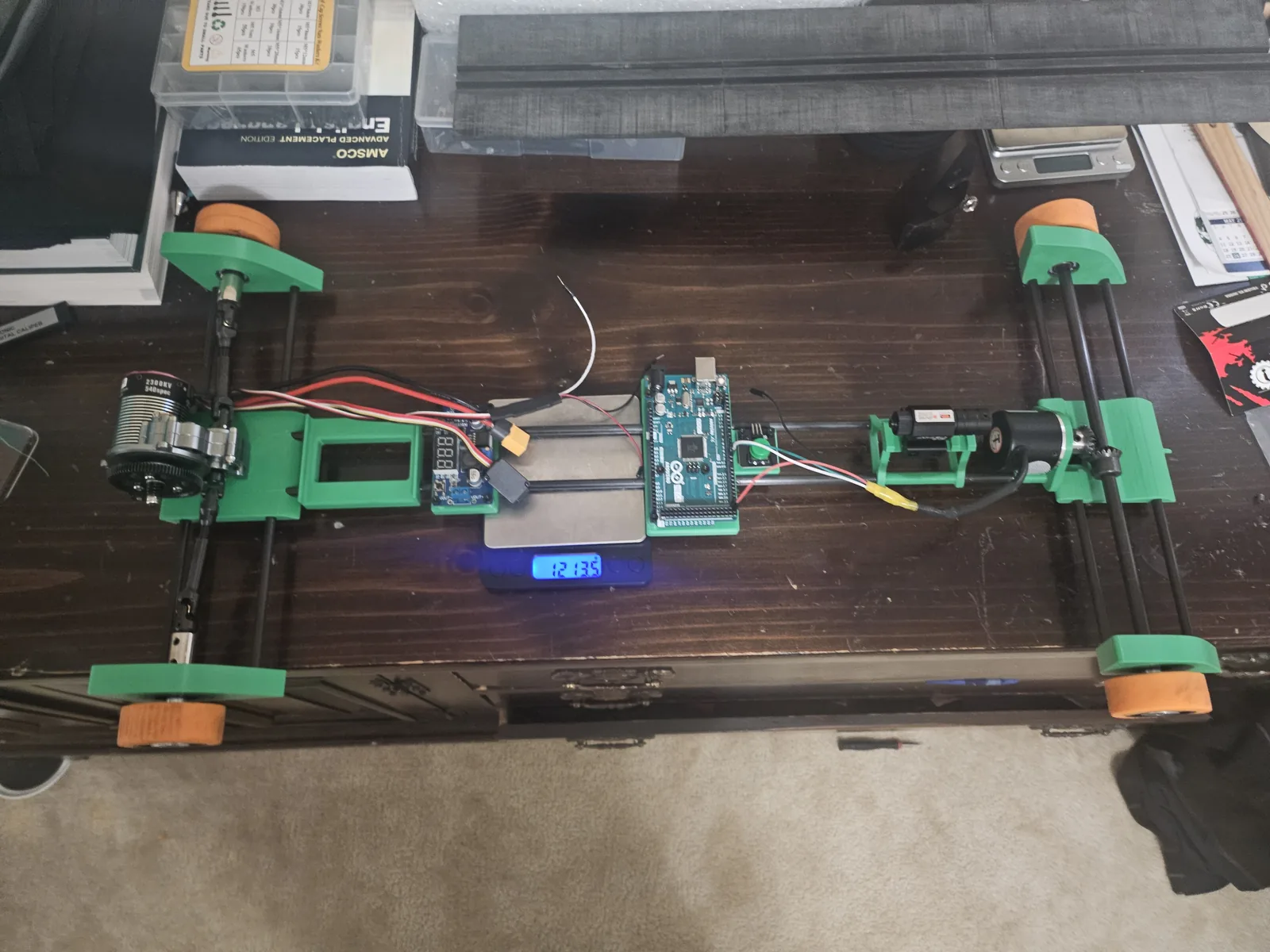
Developed for fast, accurate straight-line runs. A lightweight triangular V1 frame evolved into a longer, wider V2 to reduce veering, while retaining the same components and control code.
Engineering process
My role
I was responsible for CAD design and vehicle testing.
The objective
Complete a straight-line run as quickly as possible while reaching a specified target distance. The team prioritized speed first, then refined the distance calculations and control settings.
V1 — a lightweight starting point
The first version used a lightweight, rigid triangular frame, a brushless motor with an electronic speed controller (ESC), and a quadrature encoder at the front. The wheel layout paired smaller front tires with larger rear tires, and the gearing was adjusted to favor drive torque.
V2 — improving straight-line stability
Once speed and distance control were established, testing showed that V1 still veered during runs. V2 used a longer, wider frame to improve straight-line stability and reduce sensitivity to floor irregularities. The drivetrain, electronics, and code stayed the same across both versions.
Testing and refinement
Vehicle testing showed improved tracking and target-distance accuracy with the larger frame. Adjusting rod tension allowed quick corrections to frame alignment and imbalance, helping address the remaining veering issues.
How the control system works
Encoder feedback provides position and speed estimates. A distance-based velocity profile sets the requested speed, and the controller adjusts the ESC signal. Serial output records position, requested speed, measured speed, and motor command.
Explore the build
Chassis & electronics
The 2025 vehicle with its frame, drivetrain, controller, and wiring visible.
Open photoV1 testing
The original 2025 vehicle during a floor test.
Open video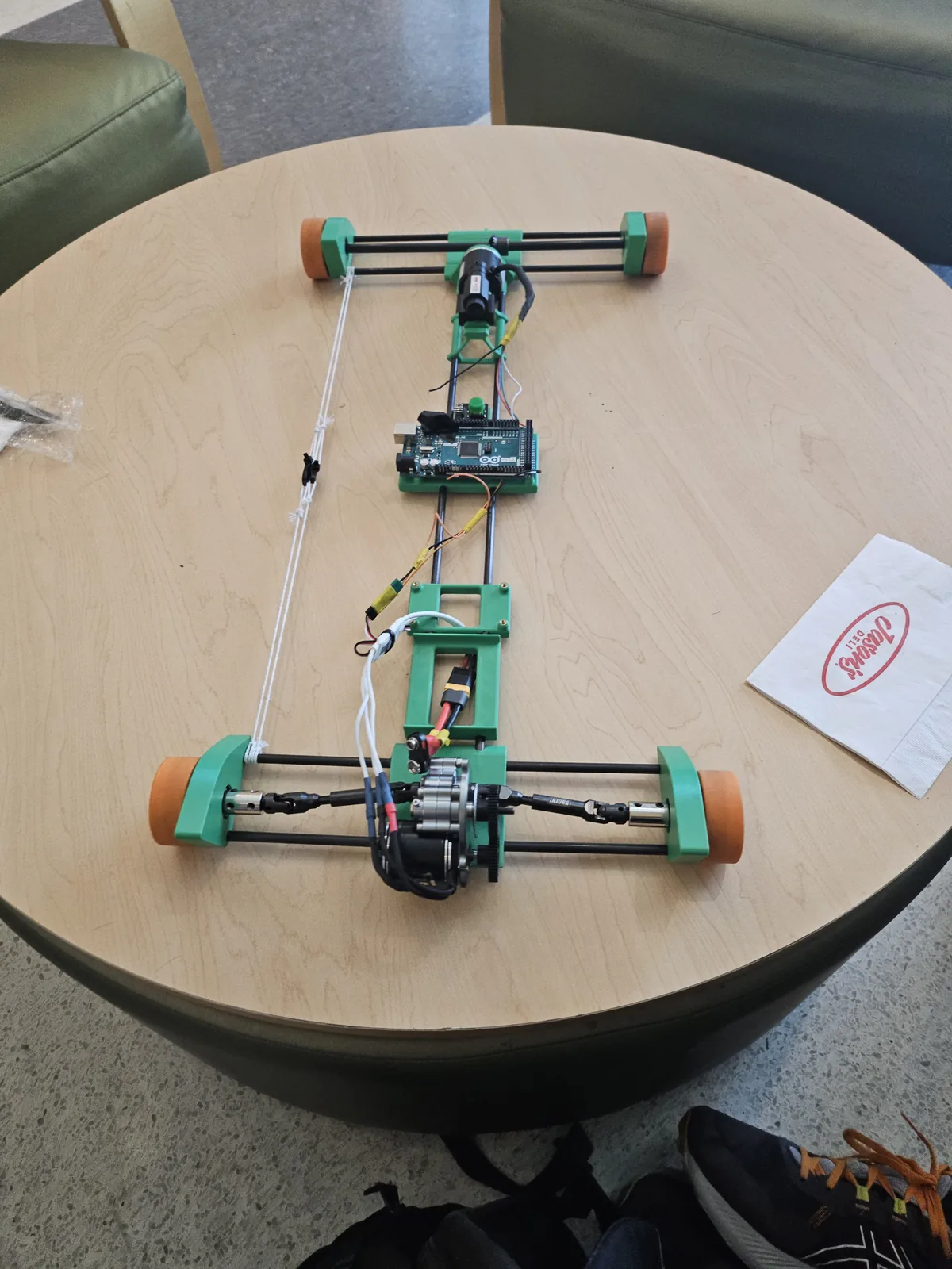
Frame layout
A full-length view of the 2025 vehicle.
Open photoVersion 2 of the 2025 EV design.
Encoder feedback control
Estimates position and speed from a quadrature encoder, sets speed according to distance travelled, and adjusts the motor controller output. Both frame versions use this program.
- Encoder resolution
- 2,400 counts/rev
- Wheel diameter
- 50.8 mm
- Libraries
- Encoder · Servo
The 8 m distance setting includes a 0.7 m offset, giving a 7.3 m software stopping target.
#include <Arduino.h>
#include <Encoder.h>
#include <Servo.h>

// Encoder setup
Encoder myEnc(20, 21);
const int PPR = 600;
const int countsPerRev = PPR * 4; // 2400 for quadrature

// Wheel & motion constants
const float wheelDiameter = 0.0508;
const float wheelCircumference = PI * wheelDiameter;

// Control pins
const int escPin = 9;
const int buttonPin = 12;
Servo motor;

// Trapezoid motion profile
float Distance = 8;
float targetDistance = Distance - .7;
float accelDistance = 1.25;
float decelDistance = 4.0;
float maxVelocity = 3.0; // meters per second

// PID control
float Kp = 3000; // Tune these
float Ki = 0;
float Kd = 100;

float desiredVelocity = 0;
float actualVelocity = 0;
float lastPosition = 0;
float lastError = 0;
float integral = 0;

// ESC pulse range
const int neutralPWM = 1500;
const int minPWM = 1550;
const int maxPWM = 1600;

// State
bool isMoving = false;
unsigned long lastUpdateTime = 0;
unsigned long startTime = 0;

void setup() {
  motor.attach(escPin);
  motor.writeMicroseconds(neutralPWM);
  pinMode(buttonPin, INPUT_PULLUP);
  Serial.begin(9600);
  Serial.println("Ready");
}

void loop() {
  long encoderCounts = myEnc.read();
  float currentPosition = (encoderCounts / (float)countsPerRev) * wheelCircumference;

  unsigned long now = millis();
  float dt = (now - lastUpdateTime) / 1000.0;

  // Start motion
  if (digitalRead(buttonPin) == LOW && !isMoving) {
    isMoving = true;
    myEnc.write(0);
    lastPosition = 0;
    lastUpdateTime = now;
    startTime = now;
    Serial.println("Motion started");
  }

  if (!isMoving) return;

  // Calculate actual velocity
  if (dt > 0.01) {
    actualVelocity = (currentPosition - lastPosition) / dt;
    lastPosition = currentPosition;
    lastUpdateTime = now;
  }

  // Compute distance remaining
  float distanceRemaining = targetDistance - currentPosition;

  // Check if motion is complete
  if (distanceRemaining <= 0) {
    motor.writeMicroseconds(neutralPWM);
    isMoving = false;
    Serial.println("Target reached.");
    return;
  }

  // Trapezoidal motion profile
  if (currentPosition < accelDistance) {
    float factor = currentPosition / accelDistance;
    desiredVelocity = maxVelocity * constrain(factor, 0.0, 1.0);
  } else if (currentPosition >= accelDistance && currentPosition < (targetDistance - decelDistance)) {
    desiredVelocity = maxVelocity;
  } else {
    float factor = distanceRemaining / decelDistance;
    desiredVelocity = maxVelocity * constrain(factor, 0.0, 1.0);
  }

  // PID velocity control
  float error = desiredVelocity - actualVelocity;
  integral += error * dt;
  float derivative = (error - lastError) / dt;
  float output = Kp * error + Ki * integral + Kd * derivative;
  lastError = error;

  // Convert PID output to PWM signal
  int pwmSignal = neutralPWM + output;
  pwmSignal = constrain(pwmSignal, minPWM, maxPWM);
  motor.writeMicroseconds(pwmSignal);
  //pio run -e mega_comp -t upload

  // Debug output
  Serial.print("Pos: "); Serial.print(currentPosition, 3);
  Serial.print(" m, Vset: "); Serial.print(desiredVelocity, 2);
  Serial.print(" m/s, Vact: "); Serial.print(actualVelocity, 2);
  Serial.print(" m/s, PWM: "); Serial.println(pwmSignal);
}